Digital System Design Using Fsms A Practical Learning Approach
174,99 €
inkl. gesetzl. MwSt.,
Beschreibung
Produktdetails
Einband
Gebundene Ausgabe
Erscheinungsdatum
28.06.2021
Verlag
John Wiley & SonsSeitenzahl
352
Maße (L/B/H)
25/17,5/2,4 cm
Gewicht
737 g
Auflage
1. Auflage
Sprache
Englisch
ISBN
978-1-119-78270-4
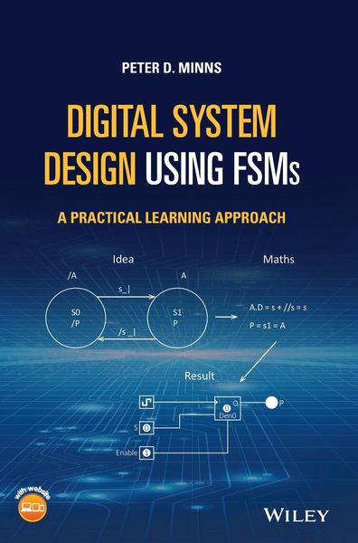
DIGITAL SYSTEM DESIGN USING FSMS
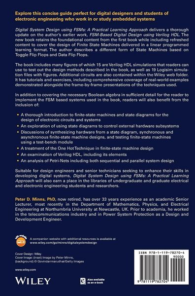
Explore this concise guide perfect for digital designers and students of electronic engineering who work in or study embedded systems
Digital System Design using FSMs: A Practical Learning Approach delivers a thorough update on the author's earlier work, FSM-Based Digital Design using Verilog HDL. The new book retains the foundational content from the first book while including refreshed content to cover the design of Finite State Machines delivered in a linear programmed learning format. The author describes a different form of State Machines based on Toggle Flip Flops and Data Flip Flops.
The book includes many figures of which 15 are Verilog HDL simulations that readers can use to test out the design methods described in the book, as well as 19 Logisim simulation files with figures. Additional circuits are also contained within the Wiley web folder. It has tutorials and exercises, including comprehensive coverage of real-world examples demonstrated alongside the frame-by-frame presentations of the techniques used.
In addition to covering the necessary Boolean algebra in sufficient detail for the reader to implement the FSM based systems used in the book, readers will also benefit from the inclusion of:
- A thorough introduction to finite-state machines and state diagrams for the design of electronic circuits and systems
- An exploration of using state diagrams to control external hardware subsystems
- Discussions of synthesizing hardware from a state diagram, synchronous and asynchronous finite-state machine designs, and testing finite-state machines using a test-bench module
- A treatment of the One Hot Technique in finite-state machine design
- An examination of Verilog HDL, including its elements
- An analysis of Petri-Nets including both sequential and parallel system design
Suitable for design engineers and senior technicians seeking to enhance their skills in developing digital systems, Digital System Design using FSMs: A Practical Learning Approach will also earn a place in the libraries of undergraduate and graduate electrical and electronic engineering students and researchers.
Noch keine Bewertungen vorhanden
Verfassen Sie die erste Bewertung zu diesem Artikel
Helfen Sie anderen Kundinnen und Kunden durch Ihre Meinung.
Kurze Frage zu unserer Seite
Vielen Dank für Ihr Feedback
Wir nutzen Ihr Feedback, um unsere Produktseiten zu verbessern. Bitte haben Sie Verständnis, dass wir Ihnen keine Rückmeldung geben können. Falls Sie Kontakt mit uns aufnehmen möchten, können Sie sich aber gerne an unseren Kund*innenservice wenden.
zum Kundenservice